
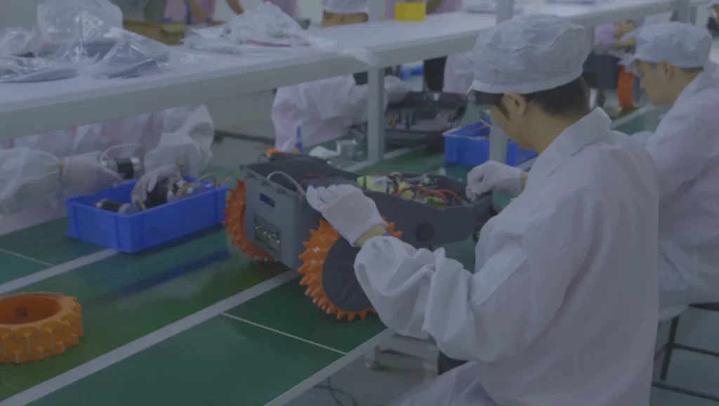








 As robotic lawn mowers continue to evolve, standardized control boards are no longer sufficient to meet the performance and functional requirements of different products. Whether it’s RTK navigation, visual obstacle avoidance, or remote control, implementing these features relies on a well-designed PCBA.
This article provides a detailed, step-by-step guide to customizing a suitable PCBA solution for robotic lawn mowers, covering everything from requirements analysis and hardware architecture to functional module configuration and mass-production validation.
Step 1: Define the Product Requirements for Robotic Lawn Mowers
Different application scenarios, feature configurations, and cost targets directly influence the PCBA architecture design. If requirements are not clearly defined early on, it can easily lead to insufficient performance, redundant features, or cost overruns.
1. Target Lawn Area
For example:
- Small residential lawns (300–800 m²)
- Medium to large residential properties (800–2,000 m²)
- Commercial complexes or golf courses (over 2,000 m²)
The larger the lawn area, the higher the system requirements, typically necessitating longer battery life, higher navigation accuracy, and greater computational power. Therefore, the PCBA design must prioritize power management, motor drive capability, navigation solutions, and MCU performance.
For example, A 500 m² residential setting typically requires only basic navigation. In contrast, a 3,000 m² or larger setting often necessitates RTK navigation, multi-zone management, and more complex path planning, significantly increasing hardware resource requirements.
2. Selecting a Navigation Solution
The navigation system is a core decision factor in PCBA design and directly impacts the overall architecture.
Common solutions include:
- Boundary-line navigation
- GPS navigation
- RTK high-precision positioning
- Visual navigation
- Multi-sensor fusion navigation
The hardware requirements vary significantly across these solutions. For example, the boundary-line solution has lower computational demands and offers controllable costs; in contrast, the RTK solution requires integrating GNSS/RTK modules and higher-performance processors for real-time positioning and path planning.
3. Define Communication and Remote Management Requirements
Common communication features include: Bluetooth, Wi-Fi, 4G/LTE, and OTA updates.
Home-use models typically rely primarily on Bluetooth or Wi-Fi connections to apps, whereas commercial models rely more heavily on 4G for remote monitoring and device management.
Communication solutions not only influence module selection but also impact PCB space, antenna layout, EMC design, and power management. Particularly in RTK solutions, improper placement of GNSS and communication antennas can lead to reduced positioning accuracy or unstable communication; therefore, these aspects must be planned comprehensively during the project initiation phase.
Step 2: Designing the Core Hardware Architecture of the Robotic Lawn Mower PCBA
Extended development cycles for robotic lawn mowers are typically not due to algorithmic issues but rather to insufficient coordination during the hardware architecture phase regarding compatibility among navigation, drive, and power supply systems. Therefore, in PCBA design, the main control chip, motor driver, and power management are the three core modules that must be defined first.
1. Selection of the Main Control Chip
The main control chip (MCU/MPU) is responsible for system-level coordination and control, including navigation calculations, sensor processing, motor control, and communication management. Its performance directly determines the system’s upper limit.
Selection must be based on the navigation solution:
- Boundary-line navigation: Mid-to-low-end MCUs can meet control requirements
- RTK navigation: Requires processing of GNSS/IMU data and path planning, with higher computational power requirements
- Visual navigation: Typically requires a higher-performance processor to support image processing and real-time computation
In addition to computational power, key factors to evaluate include interface resources, power consumption, supply stability, and product lifecycle to ensure long-term sustainability of mass production. For lawn mower products, mature and stable platforms are often prioritized over solutions focused on extreme performance.
2. Motor Drive System Design
The motor drive directly impacts the machine’s mobility and mowing efficiency, typically comprising travel motors, steering motors (on certain models), and deck motors.
Typical design challenges include high-power transients, such as the high current and EMI issues that occur when the cutting deck motor starts, which can trigger controller resets, communication errors, or positioning fluctuations.
Therefore, the drive design must focus on:
- Driver selection
- MOSFET thermal management
- Power isolation
- EMC design
- Overcurrent protection
to ensure stable operation under complex outdoor conditions.
3. Power Management System Design
The power system determines battery life and overall system stability; its key lies in its ability to handle transient loads, not merely battery capacity.
Typical architectures include the battery + BMS, DC-DC conversion, charging management, and protection circuits.
Practical issues often arise in scenarios involving sudden load changes. If power headroom is insufficient during motor startup or high-speed cutting disc operation, it may lead to system power loss or malfunctions in critical modules (such as GNSS or communication systems).
Design priorities should include:
- Peak current capacity
- Multi-channel power isolation
- Resistance to voltage fluctuations
- Power consumption optimization strategies
to ensure the system remains stable under high loads and during prolonged operation.
Step 3: Integrating Key Functional Modules into the Robotic Lawn Mower PCBA
Once the core hardware architecture is complete, the navigation, sensor, and communication modules must be integrated in accordance with the product’s specifications. These modules not only determine functionality but also directly impact PCB layout, EMC performance, and system stability.
1. Navigation and Positioning Modules
The navigation system directly determines the accuracy of the mowing path and operational efficiency, and typically includes GNSS, RTK, IMU, and an electronic compass.
In RTK solutions, ensuring signal integrity is critical. If the GNSS module is located near motor drivers or switching power supplies, it is prone to electromagnetic interference, which can cause positioning drift, slower satellite acquisition, or increased path errors.
Engineering practices typically involve:
- Physically isolating GNSS from high-power circuits
- Using independent grounding
- Implementing power supply filtering
to reduce EMI effects. Vision or multi-sensor solutions also require dedicated high-speed interfaces and computing resources.
2. Sensor Modules
Sensors are used to enable safety control and environmental awareness. Common types include collision, lift-off, tilt, rain, and ultrasonic sensors for obstacle avoidance.
For example:
- Lift-off detection triggers the cutting disc to stop
- Rain detection triggers a return-to-home
- Ultrasonic sensors are used for dynamic obstacle avoidance
The key issue typically lies not with the sensors themselves, but with insufficient interface and resource planning, which makes future expansion difficult. Therefore, it is recommended to reserve I/O and communication interfaces during the design phase.
3. Communication Modules
Common communication solutions include Bluetooth, Wi-Fi, and 4G, used for app control, status monitoring, OTA updates, and remote operation and maintenance.
Communication performance depends not only on the chip but also on the PCB layout. For example, placing an antenna near a motor driver or RTK module may cause signal attenuation or positioning interference.
Therefore, antenna layout, high-frequency routing, ground isolation, and EMC design must be considered simultaneously during the design phase to avoid performance issues later on.
Step 4: Optimizing PCB Design for Robotic Lawn Mowers in Outdoor Applications
Robotic lawn mowers operate continuously in outdoor environments and must withstand high temperatures, rain, dust, and fluctuating humidity levels. Compared to indoor devices, the focus of their PCB design is not on functional implementation, but on long-term reliability and environmental adaptability.
In actual projects, issues where devices function normally in the lab but fail outdoors are often attributed to inadequate protection design, EMC, and thermal management, rather than functional logic errors.
1. Waterproof and Moisture-Resistant Design
While the enclosure provides protection, it cannot completely block out moisture and condensation; therefore, protecting the PCB itself is equally critical.
Common failures include:
- Copper foil oxidation
- Connector corrosion
- Sensor drift
- Localized short circuits
Engineering solutions typically include:
- Conformal coating
- Waterproof connectors and sealed structural design
- Selection of moisture-resistant components
- Structural drainage and anti-condensation design
The core principle is: protection must extend to the PCB level and not rely solely on the device enclosure.
2. EMC and Anti-Interference Design
Robotic lawn mowers contain motor drives, power conversion systems, and wireless communication modules, making them typical high-interference systems.
Common issues include RTK positioning drift, communication packet loss, or system reboots after motor startup, which are often related to inadequate EMC design.
Key optimization areas include:
- Power supply and grounding system optimization
- Analog/digital/power zone layout
- Physical isolation of GNSS and drive circuits
- Power supply filtering and high-frequency routing control
In designs where RTK and multiple wireless modules coexist, PCB layout is often more critical than chip upgrades.
3. Thermal Design
High outdoor temperatures and prolonged operation significantly amplify power dissipation issues; thermal management capabilities directly impact system stability and lifespan.
Primary heat sources include motor drivers, MOSFETs, power modules, and the main control chip. Insufficient thermal management may lead to frequency throttling, communication anomalies, or accelerated component aging.
Common design strategies include:
- Increasing copper area and using thermally conductive vias
- Distributing heat sources across the layout
- Using heat sinks or metal structures for thermal conduction
- Controlling the concentration of high-power devices
The core objective is to maintain system stability under continuous high-load conditions, rather than merely meeting short-term test requirements.
Step 5: Ensure the Robotic Lawn Mower PCBA Meets Mass Production Requirements
The fact that a prototype works does not necessarily mean it is ready for mass production. In actual projects, common issues such as inconsistent soldering, inconsistent functionality, or unstable yield rates typically stem from insufficient consideration of manufacturing and supply chain constraints during the design phase.
Therefore, the PCBA design must incorporate a mass production perspective early on to ensure the solution is manufacturable, testable, and has a stable supply chain.
1. DFM Optimization (Design for Manufacturing)
DFM is a critical step in improving yield rates by reducing production complexity and enhancing consistency.
Core optimizations include:
- Rational component layout and spacing
- SMT mountability design
- Standardization of pads and traces
- Test point and serviceability accessibility
For example, if RTK modules, high-power drivers, and GNSS interfaces are laid out too densely, it can increase soldering difficulty and hinder future maintenance.
2. Supply Chain Stability Assessment
Lawn mowers have a long product lifecycle, so core components require a thorough assessment of supply risks, including: lifecycle, lead times, alternative material options, and supplier support capabilities.
For critical components such as MCUs, GNSS/RTK modules, motor drivers, and communication modules, alternative solutions should be planned concurrently during the project initiation phase to avoid design rework or delivery delays caused by material shortages later on.
3. Test System Design
Reliability testing must cover both production and environmental aspects:
- ICT Testing: Used to inspect soldering quality and assembly consistency
- FCT Testing: Verifies motor drive, positioning, communication, and sensor functions
- Aging Testing: Evaluates power supply and thermal stability during prolonged operation
- Environmental Testing: Covers high and low temperatures, humidity, water resistance, and vibration conditions
Among these, aging and environmental testing are particularly critical for commercial lawn mowers.
Step 6: Mitigating Risks in Robotic Lawn Mower PCBA Development Through Validation Testing
In the development of robotic lawn mower PCBs, issues often arise not during the design phase but during the validation phase. Industry experience shows that the primary causes of mass production failures or delays are typically not architectural flaws, but rather key risks that were not fully validated during the prototype stage.
Therefore, after completing the PCBA design and basic debugging, systematic testing must be conducted to validate navigation, battery life, safety features, and readiness for mass production.
1. RTK Navigation Performance Validation
RTK performance varies significantly between laboratory and real-world environments, as actual use is affected by obstructions, reflections, terrain, and electromagnetic interference.
Key verification points include:
- Positioning accuracy and stability
- GNSS satellite acquisition speed
- Recovery capability after signal loss
- Path-tracking performance in complex terrain
Testing must be conducted on real lawns or equivalent outdoor environments to assess whether product requirements are met.
2. Battery Life and Power Consumption Validation
Actual power consumption is typically higher than theoretical values and is influenced by factors such as lawn density, slope, mower deck load, and continuous communication operations.
Validation should cover all operating conditions:
- Continuous mowing test
- Maximum load test
- Low-battery operation and return-to-base
- Automatic charging cycle testing
Focus on verifying the stability of the power system under real-world loads, rather than static power consumption data.
3. Water Resistance and Environmental Reliability Verification
Relying solely on structural protection and PCB coatings is insufficient to ensure long-term outdoor reliability; the design’s effectiveness must be verified through environmental testing.
Common verification items include:
- Water resistance and sealing tests
- High and low temperature cycling tests
- Damp heat testing
- Extended outdoor operation testing
Focus on identifying issues such as condensation, corrosion, seal failure, and sensor false triggers.
4. Small-batch pilot production validation (EVT/DVT/PVT)
Prototype validation cannot address manufacturing consistency issues; therefore, pilot production is required to validate the feasibility of mass production further.
Key issues include:
- SMT placement consistency
- Component batch variations
- Fixture test compatibility
- Assembly and yield fluctuations
Design and manufacturing risks are gradually mitigated through a phased approach (EVT → DVT → PVT).
Conclusion
Overall, the development of PCBA for robotic lawn mowers is a highly systematic engineering process that requires a long-term balance among architectural design, environmental adaptation, and mass-production implementation. Any deviation at any stage can be magnified during mass production.
Therefore, engaging in close collaboration with a team possessing comprehensive engineering capabilities early in the project significantly impacts the product’s ultimate stability and time-to-market efficiency. If you are currently advancing the development of a robotic lawn mower, we recommend discussing your specific requirements with Altverse as soon as possible to establish a more actionable path for PCBA implementation from the conceptual design phase.
FAQ
What is the development cost for a custom robotic lawn mower PCBA?
The cost primarily depends on the navigation solution (boundary lines, GPS, RTK), the number of sensors, the complexity of the motor drivers, and the configuration of the communication modules. Among these, RTK and multi-sensor fusion solutions are more expensive. Additionally, system architecture design, EMC optimization, and validation testing (EVT/DVT/PVT) typically account for a larger portion of the cost than PCB design alone.
How long does the development cycle for a robotic lawn mower PCBA typically take?
It usually takes 3–9 months, depending on whether a mature platform is used and whether complex solutions such as RTK or vision systems are involved. Actual delays are often caused by hardware architecture adjustments and validation issues, rather than the PCB design itself.
What are the differences between RTK, GPS, and boundary line solutions in robotic lawn mower PCBA design?
The boundary line solution has a simple structure and low computational requirements; the GPS solution has moderate complexity; the RTK solution requires high-precision GNSS modules, MCUs/MPUs with higher computational power, and a more robust EMC design, making it the most demanding in overall PCBA requirements.
What certifications are required for robotic lawn mower PCBs?
The PCB itself is not certified separately, but the complete unit must comply with standards such as CE, FCC, RoHS, and EMC. Therefore, PCB design must incorporate constraints based on end-product certification requirements from the early stages.
Can a single PCB support multiple robotic lawn mower models?
Yes, but expansion capabilities must be reserved during the architecture phase, such as interface redundancy, modular communication design, and MCU processing power headroom; otherwise, cross-model reuse will be difficult to achieve.
What should be prioritized when selecting a development partner for robotic lawn mower PCBA?
The focus should not only be on PCB design capabilities but also on system-level integration capabilities, mass production experience, and comprehensive engineering capabilities for outdoor robotic lawn mowers, including EMC, waterproof design, and validation testing.
Contact Us Contact Altverse today to discuss your OEM or ODM robotic lawn mower project and get tailored solutions for your brand.

Expert in robotics, passionate about exploring a wide range of robots, robots that make work more efficient, exploring robots, including mobile robots, lawnmower robots.


